Thursday, October 26, 2006

Setting NX Environment Variables

Need to set an NX environment variable?

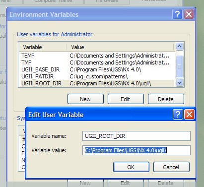
Why hunt down the ugii_env.dat file and search through the file to find the variable you need to edit, when you can organise them all via the Windows Environment Variables? When set, these will override the values set in the default ugii_env.dat file.

To get to the Environment Variables, right click on your My Computer icon and choose Properties [or select Start > Control Panel > System]. Click on the Advanced tab and then the Environment Variables button. To access my variables quickly I create a shortcut to the System window as a quick launch icon in my task bar.

Enter all your variables as User Variables. To create a new variables click the New button and enter the Variable Name and Variable Value. To disable a variable, rather than delete it, edit the variable and enter a # sign at the beginning of the variable name. Once variables have been entered, NX must be restarted to read the new values.


Using this method allows you to efficiently keep track of which variables have been modified and which ones are set. Furthermore, you don't need to edit the ugii_env.dat file each time you upgrade to a new version of NX. As new variables are introduced to NX you simply add them to your existing variables if you need to use them. The variables are also ordered alphabetically which makes them easy to find.

The only downside of using the Windows Environment Variables is that you can only see 5 variables at one time in the window. To see a complete list of variables open a command prompt window and enter "set UGII".

Monday, October 23, 2006

Defining Deformable Parts

Have you ever wanted to show a component in two forms, such as compressed and uncompressed or open and closed? Deform Part allows you to add a component to an assembly and show it in a different configuration. For example, a spring can be added to an assembly and deformed to show it in various configurations. The functionality is very similar to adding a User Defined Feature [UDF] to a part, however, the parameters you enter are applied to the component you are adding.

To create a deformable part think along the lines of creating a UDF. Name your expressions such that they are easily recognizable when it comes to creating the deformable feature; "spring_height" reads better than "p45".

Once your part is ready to create the deformation feature, select "Tools > Define Deformable Part". This will open the Deform Part wizard. The wizard creates a new "feature set" in the current part and the first step is to enter a name for the deform feature [and enter a url if you have a help page to instruct users on the deformation when adding the component]. Select the features to add to the deformable feature set and then select which expressions the user will be able to edit. A nice feature when selecting expressions is the ability to rename them to make them more understandable. For example, change length to length of spring. You can also define a controlled range of values for the expression.

Although you cannot edit a deformable feature in the component it was created in, you can obtain a list of its contents by right clicking on the feature in the Part Navigator and choosing Information. The Information Window will list the features and the values used to define the deformable feature. It should also be noted that a component can only contain a single deformable feature. Using the wizard again will delete the existing deformable feature and any assembly that contains the deformed component will show a broken icon in the Part Navigator, indicating that the association to the original [deleted] deformed feature has been broken.

When adding a deformable part to an assembly you will be presented with the usual dialogs to select the reference set, etc, and then the position of the component and then the deform dialog is raised with the title of the deformable feature set. Select [or enter] the values for the deformable expressions and choose OK to add the component.

Having added the component to an assembly and deformed it, it can be mated in the assembly and will behave just like any normal component. Once added, a new deform feature is added to the assembly and can be seen in the Part Navigator.

The deformation can be edited at any time in the assembly. Either right click the component's node in the ANT and choose Deform [click on the icon to Edit Parameters], or right click on the Deform feature in the Part Navigator and choose Edit Parameters.

Sunday, October 22, 2006

Drawing Sheet Templates

UGS provide several example drawing templates with NX4. These are located in your installation directory [C:\Program Files\UGS\NX 4.0\ugii\html_files].

This directory also contains palette files [.pax] which can be used to create a palette [a tab] on your resource bar in your NX session. The two drawing template files are called english_drawing_templates.pax and metric_drawing_templates.pax.

To read the palette files in NX, select Preferences > Palettes and select the icon for Open Palette File. Browse to the html_files directory and select the desired drawing templates pax file. Note that a new tab appears on the resource bar.

Thursday, October 19, 2006

Spaceballs - 3D Input Devices

Not to be confused with the movie, spaceballs are an essential CAD designer's tool. I've been using one for 8 years and you'll have to pry it from my cold, dead hands. Note to contractors - this will increase your productivity, so if you're on an hourly rate you might want to avoid this device.

The spaceball takes a little getting used to, but once mastered you can amaze your colleagues with your newly aquired abilities... if you have one of these you know what I'm talking about.

The ergonomic Spaceball 4000 [and the new USB 2.0 5000 model] has the ability to swap the palm rest from a left handed user to a right handed user. With 12 programmable buttons you can program macros to complete operations at the touch of a button. The 3Dconnexions website has a payback calculator which you can use to convince your manager that this device pays for itself. Alternatively, you could buy your own spaceball - there's usually a bunch for sale on ebay at a fraction of the cost of a new one.

There are several other devices which perform simlar functions. 3Dconnexion has a couple of alternatives on their website such as the Spacepilot and the Spacemouse.

NX 4 Modeling - Extruding a Face starts the Sketch App

You're intention is to extrude a face. You choose the extrude icon and select the face, however, the Sketch application starts - why?

The extrude operation is expecting that you are about to sketch the extrusion profile on the face you just selected - rather than use the edges of the selected face for the extrusion profile.

There are a couple of solutions to prevent this from happening:

  1. Change your selection intent to "Face Edges".
  2. Uncheck "Automatically Sketch on Planar Faces" in the customer defaults [found under "Modeling > Extras" in NX4.0.2 onwards].

Note that option 2 only works if selection intent is set to "Any".

NX 4 UI - Text Below Toolbar Icons

Another default installation pet peeve of mine is the toolbar icons displaying their corresponding label underneath the buttons icon. Reducing the size of the icons via the Customize dialog does not reduce the button size when text is displayed on the icons - the icons do get smaller however.

To remove the text from the buttons select "Tools > Customize", select the Toolbars page and then select the toolbar to be modified. Uncheck the option "Text Below Icon" on the right of the page and repeat these steps for each toolbar which needs to be edited.


Note: Selecting the role "Advanced - Full Menus" will automatically remove the text from beneath the icons.

NX 4 UI - Enable Full Menus

By default, the menus in NX are not fully extended - they display a double arrow at the bottom of each menu. You have to select this arrow to show the entire menu and this "feature" extends to the cascading sub menus. This is a pet peeve of mine and one of the first options I disable.

To show full menus, select "Tools > Customize" and then select the Options tab. Check the option for "Always Show Full Menus" and close the dialog. The setting will take affect when NX is restarted.

NX 4 UI - Roles

When starting NX 4.0, the experienced user will notice that only a subset of the previous version's toolbars and menu options are available. This is due to the introduction of Roles. A Role defines the layout of your NX session, including the content of the toolbars and the menus.

Provided with NX 4.0 is a collection of Roles which can be selected depending on the level of the user. On the right hand side of the NX UI you will find the resource bar. New to the resource bar is a tab titled "Roles". The corresponding Roles palette contains several folders each contsisting of a number of Roles.

The folder titled "Last Release" will only contain a role if your previous version was NX 3.0. This allows the user to change their NX 4.0 layout to how it was defined in NX 3.0. The role to select is called "user.mtx". The remaining two folders contain "Industry Specific" and "System Defaults" roles, which contain the toolbars and menu items most likely to be used by users defined by those categories.

Being an experienced user who likes to have access to everything, I chose the "Advanced with full menus" role found in the "System Defaults" folder. A novice user might want to try using the "Essentials" role as the user is not as overwhelmed with the quantity of features available in NX.


Once a role has been selected it will override the current layout [a warning is raised]. A role will contain layout settings for every application available from the NX session. On exiting the session the layout is saved to the users "defaults" location on their local hard drive and the file will be called "user.mtx", which is an XML file. The new layout can be modified at any time in NX by selecting "Tools > Customize". In this state the menus and toolbars can be edited and the changes are saved to the user's customized user.mtx file. On windows the default location of this file is: C:\Documents and Settings\user\Local Settings\Application Data\Unigraphics Solutions\NX4\ [replace "user" with your user name].

Having customized a role you can define a new role by right clicking in the Roles palette and selecting "New User Role". By defining a new role you are able to reload your customized role at any time from the roles palette. You can also copy your roles "user.mtx" file from your default location and place it in the "roles" installation folder. The default location is C:\Program Files\UGS\NX 4.0\ugii\menus\roles\. Rename your roles file to something recognizable and you can then point to it by setting the variable UGII_DEFAULT_ROLE.

Wednesday, October 18, 2006

Drafting - Preventing Leaders from Flipping

You've probably noticed that when dragging a dimension or annotation that the leader flips from one side to the other - seemingly uncontrollable. NX is attempting to make an educated guess to what it believes is the most desirable side for the leader based upon the location of the text with respect to the geometry it is attached to.

You can prevent the leader from flipping by holding down the [Ctrl] key while dragging dimensions/annotation, which maintains the current leader side.


-Mav

Modeling - Importable Part Family Template

If you've used NX for a number of versions, you may have noticed that the default column headings have changed for newer versions of NX when creating part families.

Old versions used to enter the default column heading: "Part_Name".

Newer versions now enter the default column headings: "DB_PART_NO" and "OS_PART_NAME".

The change was made to allow part families to be imported into teamcenter. If you don't use teamcenter then you may consider these columns unnecessary.

To restore the old "Part_Name" column heading open the customer defaults [File > Utilities > Customer Defaults], browse to Modeling > General, select the Miscellaneous tab and uncheck "Importable Part Family Template".


Remember to restart NX for the changes to the customer defaults to be read.


-Mav

An Introduction to Pure NX

An ambassador of UGS's NX application, I decided it was time to share the knowledge I have garnered over the years. I hope that having read the entries that follow that you leave this site have learned something new. Maybe a new tip/trick or a better understanding of how the application functions, but enough that you'll return and maybe tell a colleague or two.

Please consider leaving comments as these will help to develop this blog further and also give me some feedback so that I know I'm helping someone out there...

-Mav